
They are the Generic Socket, Generic Plug and TS2k kits, which are detailed below: There are three Installation kits available, which between them will suit any rig. TMP cables are now also available for those rigs that need them.

The PAT board should be located as close as possible to the tap point, preferably within 50mm. In addition to the Notes links below, there is also a Gallery of installation picture details, including images from rigs for which there are no formal notes.Īlthough some of the documents below, and the pictures you will see, show a coax connection from the rig into the PAT board, I recommend that you use a short length of fine single wire (eg wire-wrap type or similar), as this will have a lower capacitive loading on any tuned circuits that may be affected by the tap. The only difference is that the output is brought out on a flying lead – included in the GPIK installation kit. There are no notes provided for the FT857, but since it is essentially the same radio as the FT897, the connection points are the same. Instructions for installation for the rigs below may help you find the right points in your rig, even if it’s not listed.

You can also look at this file, which is in Rig order. The following information, ordered by PAT version, should help you to decide which version to request: Version However, the board can be installed in any rig. There are a few different versions of the PAT board, named according to nominal frequency of the Low Pass Filter.
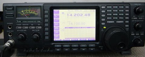
ICOM 756 PRO II DIM DISPAY SOFTWARE
Click on the link below to go to theSDRplay website – SDRuno software is also downloadable from the site. Based on availability, economics and performance, hupRF recommends the SDRplay range as suitable SDR’s for use with PAT boards. There are many on the market, and most are compatible with more that one software package. In larger rigs it can easily be ‘lost’ in a dark corner! In addition to the high input impedance buffer, the PCB also provides for a low pass filter and an output attenuator.įor the detailed description of the circuit and its operation, see hereīoth kits and assembled units are available – please go to the Orders & Prices page. The PCB is just 40 x 25mm (approx 1.6″ x 1″), and fits nicely in an FT817. This article is reproduced with the permission of the RSGB. See also the Radcom November 2014 Technical Feature article on the PAT board and its applications. This circuit, which was presented as an entry level SMD construction project at the 2013 RSGB Convention, allows the IF of a rig to be tapped off at high impedance, and brought out to an external SDR, to give a panoramic display. Check out the PAT Gallery pages from the side bar menu.


 0 kommentar(er)
